KEY FEATURES

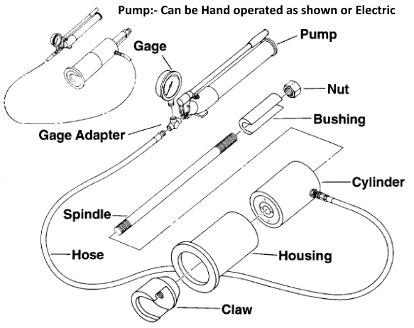
The pull tester consists of two assemblies: the hydraulic portion which includes the cylinder, gage, pump, hose and adapter; and the mechanical portion which includes the claw, housing, U-shaped bushing, spindle and nut.

With the bushing removed, the claw can be slid over the pull collar which has been installed with the stabilizer. When the housing are cylinder are raised, the bushing can be inserted between the nut and the cylinder. The nut is then tightened to take up slack.

The pump is then actuated to raise cylinder pressure, pulling the stabilizer slightly out of the hole through the bearing plate.

Maximum gage reading at slip indicates the holding force. The device can be used for slip loads up to 20 US tons (18.2 metric tons).

Image module

ORDER INFORMATION

SS46 & 39pull tester
Description Weight kg CPN
Pull tester assembly 23.8 90321597
Hydraulic parts
Cylinder (20 Tonne Alum) 5.2 90320178
Gage (1-30 Tonne) 0.7 95531
Pump (28V Enerpac) 10 89450006
Hydraulic hose (3mtr) 2 90320164
Gage adapter 0.2 90321894
Mechanical parts
Claw 1.5 90320896
Housing (alum) 2.5 72233422A
Bushing 0.5 72233430
Spindle & Hex Nut 1.2 90321845

SPLIT SET STABILIZER PULL TEST PROCEDURE – SS46, SS39 & SS33

1. Ensure that the area to be worked in is safe from all hazards e.g. loose rock

2. Ensure that all personal are wearing the appropriate PPE

3. The Pull Tester consists of two assemblies: the hydraulic portion which includes the cylinder, gauge, pump, hose and adapter; and the mechanical portion which include the claw, housing, spindle and nut. Check that all are in good working order.

4. Attach the pull claw over the top of the pull collar with the gap of the claw facing down. This prevents the claw from dislodging from the pull collar. The pull collar has to be attached to the Split Set before installation.

5. Place the housing and hydraulic cylinder over the spindle and claw, and hand tighten the spindle nut until all portions are held in place. The piston end of the hydraulic cylinder should be facing away from the rock face.

6. Place the pump (with gauge attached) in an area that does not expose personal to potential hazards e.g. rock falls. Please note that no personal should stand directly behind the pull tester whilst testing is taking place.

7. The pump is then actuated to raise cylinder pressure, until a pre determined loading is reached, or the Split Set slips.

8. The maximum gauge reading at slip or the pre determined limit indicates the holding force of the Split Set.

Townsville – North Queensland

Phone: (07) 4774 6464 (Option 3)

Perth - Western Australia

Phone: (08) 9458 1188

Sydney - New South Wales

Phone: (02) 9832 3377

Brisbane - SE Queensland

Phone: (07) 4774 6464 (option 3)

Townsville – North Queensland

Phone: (07) 4774 6464 (Option 3)

Perth - Western Australia

Phone: (08) 9458 1188

Sydney - New South Wales

Phone: (02) 9832 3377

Brisbane - SE Queensland

Phone: (07) 4774 6464 (option 3)